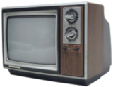
Today, just about all monitors and screens are digital (typically using an LCD or Plasma technology), but a decade or two ago, computer displays were based on the analog technology inherited from TV sets.
These analog displays were constructed around Cathode Rays Tubes (commonly referred to as CRTs).
| |Analog TV has a fascinating history from when broadcasts were first started (in Black and White), through to the adoption of color TV (using a totally backwards-compatible system with the earlier monochrome standard), through to cable, and now digital.Analog TV transmissions and their display technology really were clever inventions (and the addition of colour is another inspiring innovation). It’s worth taking a look about how these devices work, and how they were designed, using the technology of the day.|
Analog TV transmissions and their display technology really were clever inventions (and the addition of colour is another inspiring innovation). It’s worth taking a look about how these devices work, and how they were designed, using the technology of the day.
After a couple of false starts, an analog colour TV system, that was backwards compatible with black and white, became standard in 1953, and remained unchanged until the take-over by digital TV broadcasts in the early 2000’s.
Early Days
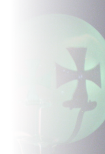
The history of cathode ray tubes dates back to the late 1800’s. In 1869, a German physicist called Johann Wilhelm Hittorf noticed that ‘rays’ (which we now know are electrons), emitted from a cathode, travelled in straight lines and could be used to cast shadows, from a cross mask, onto a phosphor coated glass.
|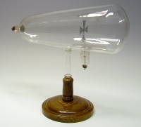 |The tubes themselves were manufactured from glass to structurally keep them stable as they needed to be evacuated to near vacuum to enable to the electrons to flow unimpeded. The first cathodes were ‘cold’, but later designs used a filament through which current was passed to “boil off” electrons (thermionic emission).Using a high-potential (typically thousands of volts), these electrons were accelerated toward a phosphor coating on the inside (named because of the phenomenon of phosphorescence, not because of the element Phosphor) screen where they generated light (luminesced).A few years later it was shown these rays could be deflected by electrical and magnetic fields.|
Using a high-potential (typically thousands of volts), these electrons were accelerated toward a phosphor coating on the inside (named because of the phenomenon of phosphorescence, not because of the element Phosphor) screen where they generated light (luminesced).
Simple CRT
Below is a (very simplified) schematic for a basic CRT tube. A heated cathode generates electrons and, using electric potential, some of these are accelerated through a control grid. A high potential at the control grid collects a lot of the electrons (producing a bright dot on the screen), a lower potential produces a less bright spot. By varying this potential, the intensity of the dot on the screen can be varied.
Other anodes are used to focus the beam, and also to accelerate the electrons. Two sets of coils generate magnetic fields which can deflect the beam horizontally and vertically. Finally, the beam hits the inside surface of the tube generating light.
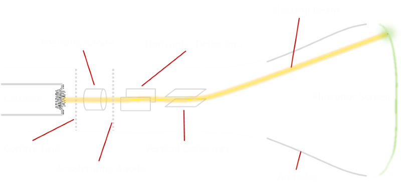
The inside of the bell-end of the tube is also coated with a conductive carbon-based coating (typically referred by it’s trade name AquaDAG: “Aqueous Deflocculated Acheson Graphite”). This also acts as a secondary anode (completing the circuit, collecting the electrons that hit the screen), but also helps act as a ‘buffer’ keeping the beam collimated and less susceptible to external magnetic and electrical fields.
| |By varying the potential of the control grid, the number of electrons hitting the phosphor can be controlled, and thus the brightness the electron beam makes as it strikes the end of the tube.By applying varying currents to the horizontal and vertical deflection coils, various strengths of magnetic fields can be generated which will deviate the charged electron beam.|
By applying varying currents to the horizontal and vertical deflection coils, various strengths of magnetic fields can be generated which will deviate the charged electron beam.
By adjusting these parameters it’s possible to control the beam and move it anywhere on the screen, and specify it’s brightness. By applying alternating parameters, the beam can be steered, and swept over the screen.
As the beam sweeps over the screen, it luminescences the coating where it hits. This luminescence decays of over time, but to generate a image, the beam is controlled in a raster fashion to sweep over the entire screen multiple times a second, continuously repainting. Persistence of vision, and the decay time of the phosphor combine to give the illusion of a continuous image.
Through the application of two sawtooth waves to the deflection coils (a high frequency one applied to the horizontal coils to sweep the beam at uniform speed from left to right, followed by a rapid return to the left, and a lower frequency wave applied to the vertical coils to slowly move the beam down the screen, then back up to the top), the beam can be directed to sweep over the screen as a series of lines.
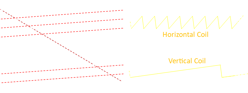
The slower vertical scan sawtooth gradually moves the electron beam down down the screen at a continuous rate (until the rapid vertical retrace, or flyback). This would mean the horizontal scan lines would slope slightly down to the right, but this can be compensated for by rotate the vertical deflection coil slightly to balance this out.
There is also a horizontal retrace that sends the beam back to the left side of the screen to start painting the next line.
NTSC (The National Telecommunication System Committee), the standard in the USA, in 1953, defined a TV picture to have 525 lines. In other regions of the World, the standards are sometimes different. For instance, in Europe the standard is 625 lines.
In NTSC, the horizontal saw-tooth wave has a frequency of 15,750 Hz (meaning it takes approx 63.5 millionths of a second to draw a single line). The vertical saw-tooth has a frequency of only 60 Hz, to allow the screen to be repainted 60 times in a second. (Those good at math might see that 15,750 divided by 60 is not an integer; there is a reason for this, but you’ll have to wait few more paragraphs for an explanation).
Blanking, Retrace, and Scanlines
It’s important that the electron beam is turned off as it retraces, otherwise the image on the screen would be messed up. Another problem is that we don’t want the image to drift from side to side and get skewed.
A frame of TV picture is transmitted as a series of lines, called scan lines. For each line, how the brightness (luminosity) varies across its width is described.
Below is a representation of part of a black and white analog transmission. It is called a composite signal because, in addition to holding the picture information, it contains the timing components. It is an amplitude modulated signal. Each frame of the TV picture is transmitted as a chain of scan line pulses. Depending on the geographic region there could be 525 scan lines in each frame (In the USA and Japan), or 625 (much of the rest of the World), but more of this later …

The amplitude of the signal represents the luminescence (brightness) of the spot on the screen at that point.
A high amplitude represents a bright (white) spot, and lower amplitudes represent darker dots. There is a level just below the darkest possible level called the blanking level (A level ‘blacker than black’). At, or below, this blanking voltage, the electron gun should be off. It’s during this time, called the blanking interval, that the beam sweeps back to the left (horizontal retrace), to paint the next line down, and it does so without rendering any image.
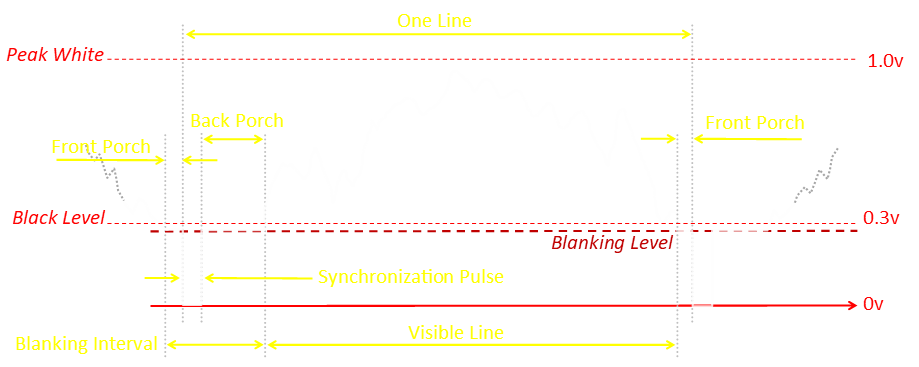
To stop subsequent lines skewing from side to side through timing drift, at the start of each scan line is a synchronization pulse. This reminds the rendering receiver exactly when each line needs to start. This synchronization pulse is 4.7µS long. Just before this pulse is an even shorter Front Porch gap of 1.5µS (to allow older TVs to stablize voltages and prevent line interference), and downstream of the synchronization pulse is a longer Back Porch, at the blanking level voltage. As we will see later, this back porch has an additional use for color TV signals. During the entire time between the front porch, through the synchronization pulse through the the back porch, the signal is below the blanking internal, and the electron gun is off. It is during this blanking interval that the gun sweeps around to back ready to draw the next line.
Here is an (exaggeration) of what might happen to the image if there were not horizontal synchronization pulses generated to define the start of each line. Without the sync pulses ‘reminding’ the receiver exactly when each line begins, the analog technology used might drift slightly.


Below is a animation showing a single scan line a small image (containing just 64 vertical lines).
You can use the UP and DOWN buttons to select which of the lines from the image is rendered (when stopped), or see how the image is painted at various speeds. The rendered line is shown below the graph of the luminosity values. Using SLOW, MEDIUM, or FAST you can see the relationship between the voltage of the signal and brightness of the beam on the screen, and how this generates lines.
| |To stop ragged edges, and issues with a potential sharp edge when the line started or ended with a bright signal, old TV’s typically didn’t display all the transmitted image. A small part of the the left and right of each line was cropped off, as was a little at the top and bottom (sort of like zooming in slightly). This was referred to as Overscan. This was a useful safety feature in the days of analog TV, whose components were, well, analog, and could drift. In digital televisions, this is no longer an issue. You probably have controls on your digital TV or cable box to turn off overscan and get more of the picture you are paying for!|
The non-visible lines clipped out of the viewed area were later used to add additional metadata to the image, such as closed-captions, and in the UK, the awesome Teletext service.
More importantly, the first few lines contain vertical blanking pulses/timing to return the beam back to the top.
Further down the rabbit hole
It’s not quite as simple as we’ve described it above. When television was first invented, bandwidth was limited, and there is still the desire to keep the refresh rate as high as possible to prevent flicker, and to preserve the persistence of vision in which a rapidly flickering image is interpreted by the brain as a continuous image. Depending on your region, a TV picture refreshes 50 or 60 times per second.
|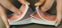 |A solution to this dilemma is interlacing. Rather than repaint the entire image 60 times each second, the screen is still refreshed at that rate, but on each frame, only half the image is updated. Every other line is skipped between frames. Alternately, the even number, then the odd numbered, scan lines are transmitted. These mesh together like a fingers (or a perfect riffle shuffle of a deck of cards).|
|Interlacing halves the bandwidth requirements.It’s not a perfect solution as, if objects are moving rapidly, they are at different positions on the odd and even lines. This can cause image ‘tearing’, and the edges of objects can look like they are being viewed through a comb.If the signal is transmitted as frames of every other line, this is called Interlaced signal. For the bandwidth preservation reasons described above, this is how over-the-air TV transmissions were broadcast.When every line of a frame is rendered, in order, this is called progressive scan.|
|A solution to this dilemma is interlacing. Rather than repaint the entire image 60 times each second, the screen is still refreshed at that rate, but on each frame, only half the image is updated. Every other line is skipped between frames. Alternately, the even number, then the odd numbered, scan lines are transmitted. These mesh together like a fingers (or a perfect riffle shuffle of a deck of cards).|
|Interlacing halves the bandwidth requirements.It’s not a perfect solution as, if objects are moving rapidly, they are at different positions on the odd and even lines. This can cause image ‘tearing’, and the edges of objects can look like they are being viewed through a comb.If the signal is transmitted as frames of every other line, this is called Interlaced signal. For the bandwidth preservation reasons described above, this is how over-the-air TV transmissions were broadcast.When every line of a frame is rendered, in order, this is called progressive scan.| |
|
It’s not a perfect solution as, if objects are moving rapidly, they are at different positions on the odd and even lines. This can cause image ‘tearing’, and the edges of objects can look like they are being viewed through a comb.
When every line of a frame is rendered, in order, this is called progressive scan.
The classification of a transmission is usually indicated by the number of lines, followed by a lower-case i or p to represent the type of scan. You may see references today to signals such as 1080i, 720p, 480i …
A 720p signal has a vertical resolution of 720 lines, and is rendered progressively.
Examples
Here are a couple of interactive animations showing the different rendering styles. The first is progressive scan. Here each line is drawn, sequentially, in order down the screen.
Next is interlaced, first the odd, then the even lines are drawn. In any frame, only have the lines are drawn.
Last trip down the rabbit hole
Analog TV broadcast were all performed using interlaced scan, and in the NTSC standard an image had 525 lines.
This is an odd number.
525 ÷ 2 = 262½, so each interlaced frame requires 262½ lines to be drawn. (This is the explanation for the non-integer multiple of the horizontal saw-tooth frequency we mentioned earlier: 262½ × 60 Hz = 15,750 Hz).
This means we have to draw two half-lines in every frame.
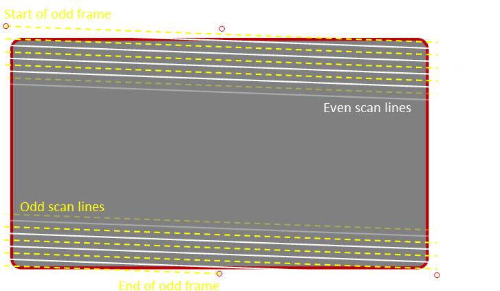
In odd frames of the picture, lines start at the top left, and only half a line is drawn as the last line of the frame. Even frames start their first line half-way across the screen, and finish in the lower right. Because of over-scan (described early), these half-lines are never seen.
In Europe, the PAL system uses 625 lines, with a refresh rate of 50 Hz, so the horizontal frequency is 15,625 Hz.
Confusing Protocol
Unfortunately, the adjectives odd/even come up too many times when describing video, and get confusingly overused. Numerically, lines are labeled based on the order they are rendered (scan line ordering in the signal). This means, because of interlacing, adjacent lines on the display are not numerically adjacent. In interlaced video, there are two fields in every frame. Typically these are labeled field 1 and field 2 (odd and even). Field 2 starts with the sync pulse midway through the line, so even numbered lines are on field 2. But what about the half lines, how to you label these? Also, should you call the first (half) line zero or one? It seems there are two standards: Time Line Numbering and Field Line Numbering. Unless you work in the industry, I’d not worry about this.
Vertical Blanking
An additional set of pulses (below blanking level) are inserted to describe the start of each frame. These provide vertical synchronization and also allow the beam to sweep back up to the top of the screen to render the next frame. This is the vertical blanking interval.
These trains of pulses are more complex and comprise a series of pre-equalization pulses, followed by field sync Vertical pulses (called broad pulses), followed by post-equalization pulses before the scan lines for the next frame are delivered.
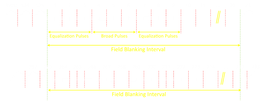
The pre-equalization pulses are six pulses (at half the pulse width of the horizontal sync pulses, but twice the frequency so that they occupy the same time period of three regular lines); the midline sync pulse is ignored, keeping the timing correct, and by making the pulses half the width, the energy content is the same. Next are six broad pulses, delivered over the time of three additional lines. Finally a set of post-equalization pulses, which are identical to the pre-equalization pulses. In total, these pulses take the space of nine scan lines. In additional to the vertical sync pulses, a total of the first 20 lines of every frame are reserved for the vertical blanking and additional control information (V-chip, stereo audio, subtitles …). These 20 lines are called the vertical blanking interval, and all signals here are not rendered. What this means is that, on a 525 analog signal, at most, the highest resolution is 485 lines. (For PAL, the vertical blanking interval is 25 lines, resulting in an active field resolution of 575 lines).
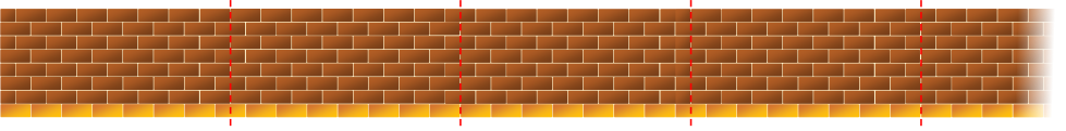
Just because there are half lines, do not think of these as discontinuities. The train of pulses is continuous and at constant rate, it’s just that there is a non-integral number of lines in a frame. A good analogy for how this works is imagine the signal like a brick wall built using a regular running bond (called a stretcher bond). In any small section of wall, it’s possible to identify even and odd frames, but if these are built together alternating between odd and even frames, the bricks are in courses that are continuous. (In this analogy, the vertical mortar lines between bricks are the horizontal sync pulses, and where the transitions are between odd and even frames are the vertical sync pulses).
Here is a continuous wall when the frames alternate:
Why 525 lines?
A common question is why 525 lines was chosen as the vertical line resolution for NTSC (or 625 for PAL); These sound like pretty obscure numbers. Obviously, there is a desire to make them as high as possible (for the best picture quality), but also the compromise of the needed bandwidth wanting to make them as small as possible. In fact, in the UK, where I grew up, before we had the 625 format, old B TV’s had 405 lines and, for a while, the BBC transmitted both formats - ending broadcast as laster as 1985. In France, they had an 819 line standard for a while (the first HD? Around the time of WWII - impressive, but a bandwidth hog), with 441 before that. At first glance, these really do seem like arbitrary numbers.
The answer to the puzzle is because of ratios. Because of interlacing, the timing for the horizontal and vertical timebases needed to be precise. The time signals were generated through a series of electronic dividing circuits. Each division is a by an odd number. Technology constraints of the 30’s and 40’s necessitated using only integers (preferably no greater than 7 for stability).
405 = 3 × 3 × 3 × 3 × 5
441 = 3 × 3 × 7 × 7
525 = 3 × 5 × 5 × 7
625 = 5 × 5 × 5 × 5
819 = 3 × 3 × 7 × 13
Why an odd number of lines?
I should probably have answered this question first, rather than burying it right here, but to answer this you need an appreciation of how the analog system worked.
The question is, why devise a system to with an odd number of lines in the first place, and cause all this headache? Wouldn’t it be simpler to define an interlaced system with an even number of lines? The answer is yes, and for digital protocols, this is what has been done.
However, remember back to the time of when the television standards were being defined. This was in the 1930’s, before the birth of digital computers. Systems were analog, and timing was everything. The reason that half lines were invented was so that distance of the vertical retrace was the same for both the odd and even frame!, and horizontal displacement carries on at the same rate. (In the images below, the length of the red and blue lines is the same. The vertical retrace takes the same amount of time).
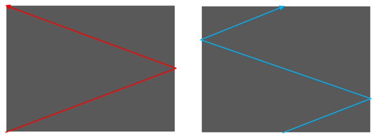
In this way, just one simple master oscillator could be used and divided down to generate all the other timing signals needed. Pretty neat!
It’s a little embarrassing how easy digital technology has trivialized some problems, and it’s easy to overlook just how clever some of these solutions were using the technology of the day.
Black and White TV stood the test of time, and for decades, the transmission format described above remained unchanged.
Color TV was the next obvious step. Interestingly, various color television systems were experimented with, dating back to the late 1920’s, but it was not until the 1950’s that sufficient progress was made to consider a standard. It was not until 1970’s that sales of color televisions overtook monochrome TV sales.
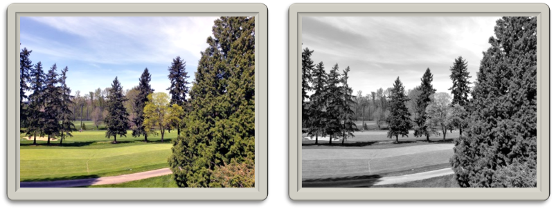
|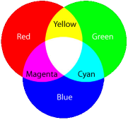 |Our eyes have two type of light detectors: Rods and Cones. Rods capture light and dark signals, and cones detect color (wavelength). The average retina contains approx 120 million rods, and about 6 million cones. Of this 6 million, these are divided into groups that are sensitive to red, green, and blue light.(The much larger number of rods means the eye has far more resolution to brightness than color; this becomes important later).As we learned in school, using the additive color principle, other colors can be created by mixing, in various quantities, red, green, and blue light.|
(The much larger number of rods means the eye has far more resolution to brightness than color; this becomes important later).
In theory, we could make a color television signal by simply broadcasting out three monochrome signals, one for each of the primary colors, and combining these at the receiver. In fact, this is what the first color TV transmissions attempted. However, it’s easy to see a downfall in this principle, and this is bandwidth. Transmitting three monochrome pictures would require three times the bandwidth! (And it’s not backwards compatible with the existing black and white sets).
Even with these issues, pioneering broadcasts were made using three signals. The receiving devices used either a mechanical or optical mechanism to recombine the image.
The mechanical systems used a spinning color wheel that held alternating panes of Red, Green, and Blue glass and a standard CRT to illuminate. By spinning the wheel (fast), and ensuring the wheel was synchronized with the transmission, the TV would rapidly display RGB images which shone through and, with persistence of vision, these merged into a full color image. It’s easy to see the limitations of this set-up.*
The optical system used lenses and mirrors, and three separate CRT tubes covered with appropriately tinted filters. These could combined onto a frosted screen to produce a color image. This, interestingly, is how, decades later, rear-projection TV’s work. However, in the early days, CRTs were not very efficient, and the resulting image was very dim. Also, the costs were astronomically high as each device was essentially three TVs (already expensive) as well as the lenses and mirrors.
*Returning full circle, modern single chip DLP projectors use a spinning color wheel!
Compatible Color
Two breakthroughs were necessary for the mass adoption of color TV and color TV broadcasts.
The first breakthrough occurred in 1954 with the introduction of the compatible color format; a way of adding color to the existing black and white format that was entirely backwards compatible. (Interestingly, prior to this, the FCC had concluded that a compatible color system was not possible and it was inevitable that a new format was needed. They had previously approved wasteful simultaneous transmissions of both black and white, and color transmissions. After some lobbying, and a little bit of legal pressure, the NTSC compatible color system was approved). With compatible color, the broadcast stations could continue to radiate only one signal, and existing old monochrome receivers would display a black and white picture, whilst a color receiver would display a color picture. Over time, as people replaced their TV’s, on their schedule, they could upgrade to color. We’ll describe this format later.
The second component needed to usefully view color TV transmissions was a CRT that could display different colors. Phosphors were already available that fluoresced at appropriate red, green, and blue colors, and there was technology available to easily screen print these onto the inside of the CRT tube. But, to work correctly, a new invention was needed.
|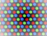 |Thousands of patches of these phosphors were arranged, in a triangular pattern, called a triad, to the inside of the screen. As the dots were very small (fractions of millimeters), when illuminating, they merged with the light from the other elements of the triad to make a color picture. Unless you were very, very close the the screen, the individually light Red, Green, and Blue dots would look like white light.|
The problem was that these dots were very, very, small; much smaller that the diameter of the electron beam. It was not possible to focus and steer the beam to hit the correct target, and only that target (It’s like trying to blow out a specific candle on a multiple candle cake birthday cake with a fire hose!)
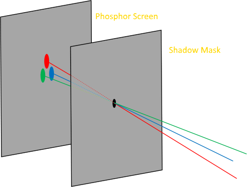 |
The breakthrough came from the invention of the Shadow Mask by the German Werner Flechsig.
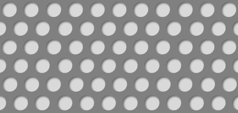
||The breakthrough came from the invention of the Shadow Mask by the German Werner Flechsig.His invention was thin sheet of metal peppered with precise a mesh of thousands of holes in a similar triangle arrangement, mounted close to the phosphor. By using three electron guns instead of one (one for each color), also arranged in a triangle, the geometry could be arranged so that each gun could only see one set of dots. (Imagine holding a sieve in front of a flashlight).(Simplified image to the left, showing a shadow mask with just one hole).|
(Simplified image to the left, showing a shadow mask with just one hole).
Note: These triads are not pixels in the traditional sense that we know from digital displays, they are simply ways to produce color, and the shadow mask is there to simply prevent the incorrect beam hitting the incorrect phosphor.
If all three electron guns were driven with the same intensity, a traditional black and white image would be displayed on the screen, but by sending different signals to the different guns, color images could be displayed.
To make the system fully backwards compatible, the next step was to hide the color information inside the black and white signal such that an old receiver will still work. This is clever. To understand how this works we’re going to have to learn a little bit about alternative ways to describe color.
(Shadow masks, whilst very clever, created a new set of problems addressed over the years with other optimizations. The masks absorbed 85% of the electrons, causing thermal issues and image brightness challenges, requiring more powerful and expensive guns. The three gun set-up also caused geometry issues at the edges of the screen).