The inspiration for this posting comes from an excellent book I’ve just read called Professor Povey’s Perplexing Problems (Pre-university Physics and Maths Puzzles with Solutions). If you enjoy the writings of Martin Gardner you’ll love this book. His book also reminds me of another title I read years ago called The Flying Circus of Physics (Oh, it appears there is a now a second edition; I’ll have to order it!)
|The inspiration for this posting comes from an excellent book I’ve just read called Professor Povey’s Perplexing Problems (Pre-university Physics and Maths Puzzles with Solutions). If you enjoy the writings of Martin Gardner you’ll love this book. His book also reminds me of another title I read years ago called The Flying Circus of Physics (Oh, it appears there is a now a second edition; I’ll have to order it!)The question is a simple one: If you have a long straight square sectioned bar, and drop it in water, what orientation will it float in?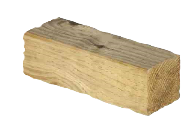 |
| |
|
| (We’re going to assume that the bar is long enough that the ratio of the length to the width is great enough that this can be considered a 2D problem). |
Which orientation will a square section float?
… or will it float at a totally different angle?
Density of wood
How will the angle it settles change with the density of the wood?
The closer the density of wood to water, the lower it will sit.
Wood with a lower relative density to water will float higher. (If the density of wood is greater than that of water then it will sink. There is class of hardwoods given the fancy name of Ironwoods that are denser than water).
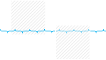
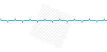
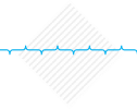
Here’s a thought experiment before we dig into the maths. Which of the diagrams below ‘look right’? If you used your gut, and wanted to guess, which orientations are possible? I’ve selected three different relative densities that Goldilocks would be proud of: Low, High and Medium.
Buoyancy
First we need to understand why things float, then we’ll look at stability.
The wood bar will float because of buoyancy. I’ve written about this concept before in the article How much does a cloud weigh?
When the bar sits (or is immersed) in water, it displaces a certain volume of water, and the weight of the water displaced provides an upwards force equal to the weight of the volume of water it displaces. The mass of the bar does not change; it still has the same amount of stuff in it.
This is called Archimedes’ Principle.
This mysterious buoyancy force is not created out of thin air, and there is no unbalanced force. The weight of the floating bar it still the same, it’s just that a lot of this force has been transfered to the water which is reacting it to the ground. Not convinced? Try this thought experiment: Imagine a kids paddling pool full of water sitting on a set of bathroom scales. Note the weight, then drop the square bar into the pool so that it floats. The bathroom scales reading will go up the same amount (the weight of the bar), irrespective if the bar was floating, or not floating.
Stability
|We’ve now determined if the bar will float or not. Next we need to take a look at stability. Why does a floating bar move to the steady state it finally reaches?Given a choice, things like to fall downhill. That is to say the pull of gravity attempts to reduce the potential energy stored in a system. Also, in accordance with Newtons First Law, for it to be in steady state (floating without accelerating or rotating), the forces acting upon it need to be in balance. Let’s look at the forces. The weight of the bar is always present and acts vertically down through the center of mass. (Because we’re in a uniform gravitational field, the center of mass and the center of gravity are the same). The gravity force acts through the centroid of the shape. The centroid of a square section bar is the center of the square.|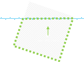 |
|
Given a choice, things like to fall downhill. That is to say the pull of gravity attempts to reduce the potential energy stored in a system. Also, in accordance with Newtons First Law, for it to be in steady state (floating without accelerating or rotating), the forces acting upon it need to be in balance.
|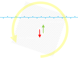 |The buoyancy force, when the system is at rest, is equal to the weight of the bar. This force acts through the centroid of the ‘hole’ in the water displaced by the bar.If these forces do not align in the same vertical plane, a torque is created. This will cause the bar to rotate. The rotation of the shape changes the geometry of the system, and the bar will carve out a different shape hole which, in turn, adjusts the center of buoyancy …What we need to determine is the state of the system when it comes to rest.|
If these forces do not align in the same vertical plane, a torque is created. This will cause the bar to rotate. The rotation of the shape changes the geometry of the system, and the bar will carve out a different shape hole which, in turn, adjusts the center of buoyancy …
Math
|The geometry of the system changes depending on both the relative density of the bar (how deep or shallow it sits overall), and the angle. Depending on these two factors, one, two, or three corners of the bar section could be under the water.If there is one corner under the water, then it’s a triangular shape under the water and the centroid is easy to calculate. If there are two corners under the water then the shape under the water is a quadrilateral. If there are three corners, the shape is a pentagon.Because the geometery is fairly complex, it’s a good candidate for a simulation.|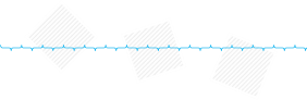 |
|
If there is one corner under the water, then it’s a triangular shape under the water and the centroid is easy to calculate. If there are two corners under the water then the shape under the water is a quadrilateral. If there are three corners, the shape is a pentagon.
Simulation
The best way to look at this is with a little interactive animation. Below is an applet that will allow some experimentation. It models a square section bar floating in fluid. The density of the fluid can be adjusted and the effect of the settling orientation observed.
Instructions:
-
The animation can be started/paused using the button in the top right.
-
The square bar can be dragged at any time to a new location to override gravity (try dragging it below water to watch it bob up, or drop it from the air!)
-
If the animation is running, clicking on the right side of the bar will slowly rotate it clockwise. The further from the center the click is, the faster the rotation. You can move and rotate at the same time. Clicking on the left side causes counter-clockwise rotation.
-
Once released, the bar will rotate and bob until it reaches steady state.
-
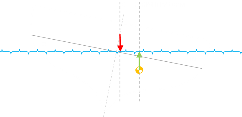
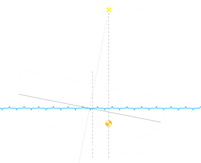
Other buttons on the right allow the toggling of if the center of gravity (rendered as the traditional checked bullseye), and the center of buoyancy (as a green dot) are rendered.
-
The buoyancy vector shows size of the force provided by the displaced water. Displaying the red vertical line helps visualize the delta between the buoyancy and the weight vector.
-
Toggling the buoyancy shape button shades the region that the upthrust is calculated by.
-
The relative density of the fluids can be adjusted from 0.05-1.10 using the four buttons underneath the label. The two outer buttons adjust +/- in increments of ±0.1, the two inner buttons in finer ±0.01 increments.
-
Finally, at the bottom, the angle of the bar can be manually adjusted. (Note - if you attempt to adjust this whilst the simulation is running, it will fight against you!)
-
The coordinates in the top left corner show the difference in height of the center of gravity above the center of buoyancy for the current configuration (Δh), and the righting arm (this is the difference in horizontal positions of the center of gravity and the center of buoyancy), Δx. A none zero value for the righting arm indicates there will be a torque, and the system will still be in rotation. (Units are based on the unit length of the bar side).
Results
What did you find out? The first surprising results is that the answer to the question about which orientation is stable is ‘it depends’.
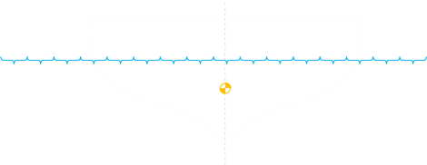
| |When the relative density of the bar is high or low, the bar will naturally settle in an orientation parallel to the water. This just looks right, and we can imagine either a water logged plank, sitting just near the surface, or a cork log floating stably on top of the water. Once in the rested state, nudging it one side or another causes it to return to the mean stable condition. This is important.|
|When the relative density is about 0.5 (so that the bar floats close to halfway in the water, after settling), it is more stable resting at 45° to the horizontal. As above, displacing the bar, or moving it, or rotating it may cause a temporary deviation, but after a while, it returns to rest condition.|
|When the relative density of the bar is high or low, the bar will naturally settle in an orientation parallel to the water. This just looks right, and we can imagine either a water logged plank, sitting just near the surface, or a cork log floating stably on top of the water. Once in the rested state, nudging it one side or another causes it to return to the mean stable condition. This is important.|
|When the relative density is about 0.5 (so that the bar floats close to halfway in the water, after settling), it is more stable resting at 45° to the horizontal. As above, displacing the bar, or moving it, or rotating it may cause a temporary deviation, but after a while, it returns to rest condition.|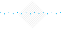 |
|
|
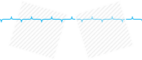
| |Did you find any others shapes? Yes, in the second surprising result it’s possible for the bar to come to rest and be stable in a non-symmetric orientation. Would you have predicted that? If you can’t find any such position, adjust the density ratio to 0.760 and wait for things to settle down. After a while, the bar will come to rest at an angle of 66.5° (or it’s reflection 113.5°).|
|It’s stable in this position because Δx, the righting moment arm, is zero (there is no torque turning the block); we can see this because the center of gravity and the center of buoyancy are aligned vertically. However, this is just part of the requirement for stability. We also need to make sure that the turning point is the correct shape: A slight change to Δx needs to result on a torque vector that attempts to restore this change; we’ll discuss more of this later.|
|Did you find any others shapes? Yes, in the second surprising result it’s possible for the bar to come to rest and be stable in a non-symmetric orientation. Would you have predicted that? If you can’t find any such position, adjust the density ratio to 0.760 and wait for things to settle down. After a while, the bar will come to rest at an angle of 66.5° (or it’s reflection 113.5°).|
|It’s stable in this position because Δx, the righting moment arm, is zero (there is no torque turning the block); we can see this because the center of gravity and the center of buoyancy are aligned vertically. However, this is just part of the requirement for stability. We also need to make sure that the turning point is the correct shape: A slight change to Δx needs to result on a torque vector that attempts to restore this change; we’ll discuss more of this later.|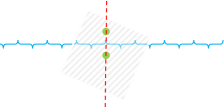 |
|
There are positions where Δx is zero but the configuration is not stable. If the moment arm grows the wrong way from this zero position with a change in angle, then the bar will continue to rotate (Imagine, for instance, a low density bar attempting to float at 45° on top of the water; like a diamond). These configurations are the equivalent of inverted pendulums (or like trying to balance a pencil upside down). As soon as the bar starts to rotate one direction, the torque generated by the unbalanced force increases the angle of deviation. This positive feedback loop accelerates the shape around until the stable orientation is reached.
Below is the graph showing the angles for stable equilibrium states over the range density ratios:
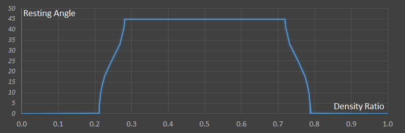
We can see that when the density ratio is low (or high) the stable angle is 0°. When the density ratio is close to 0.5, the stable angle flips to 45°.
Inbetween these two sections are regions where the cente of buoyancy aligns with the center line in stable conditions at other angles.
I find this graph super interesting. I’ve never seen reference to anything like it in any of the Physics and Engineering text books I used to study from in school.
It’s in interesting exercise in geometry to work out the centroids of the underwater sections under the various conditions of differing number of potential corners under the surface (maybe a future article?), but here, without any explanation of the derivations, are the results! You can see the range of parameters for which the bar is not stable at the boring 0° or 45°angles!

From ≈0.211 – 0.281 density ratio, and ≈0.719 – 0.789, the bar will list at a lazy angle.
Stability Charts
| |Let’s look at a couple of examples to see what is going on. We’ll look at three different density ratios.A=0.150, B=0.250, C=0.550, D=0.775|
A=0.150, B=0.250, C=0.550, D=0.775
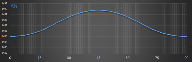
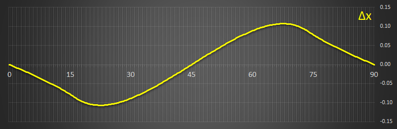
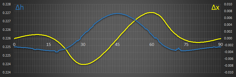
For each location, we’ll plot two graphs that depict the dynamics for all possible values of rotation of the bar with those densities. The first is a chart of the Δh (the height difference between the center of gravity and the center of buoyancy). The second chart shows the length of the righting arm Δx, and shows the horizontal displacement between the center of buoyancy and the center of gravity for every angle rotation.
(Note, I’m only rendering the graphs 0-90°, as the square has rotational symmetry beyond that).
Here is an example graph showing the difference in height between the center of gravity and center of buoyancy at every angle. This is a graph for a block of low relative density. We can see that the location where the height difference between the center of gravity and center of buoyancy is the greastest is at 0°. This corresponds to the lowest potential energy of the system.
Below is the corresponding graph showing showing the size of the horizontal moment arm away from the center or gravity. The only place that the system could be stable is at zero (where the yellow line crosses the middle axis at Δx=0), but this is only one of the requirements. As you can see, at 45° it crosses over, but it’s not stable at this point because the gradient here shows that an increasing in angle increases the moment arm. The place where it crosses over and the gradient is negative is at 0°(90°). This is the location this bar is stable.
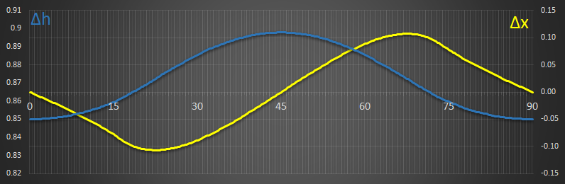
It’s useful to plot these on the same graph (note the scales change, but it’s the shapes we’re interested in):
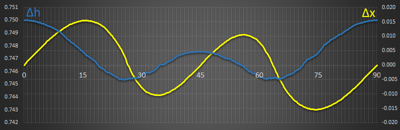
[A] Density Ratio = 0.150
 |
This system is only stable in one position, with the angle at 0°.The values for Δx (right vertical axis) are quite large, showing that quite a lot of torque would need to be applied to rotate this bar from its natural stable position. |
The values for Δx (right vertical axis) are quite large, showing that quite a lot of torque would need to be applied to rotate this bar from its natural stable position.
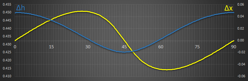
[B] Density Ratio = 0.250
 |
This density has two stable locations. These occur at approx 26.6° and 63.4°.These two points correspond to the lowest energy (minimum of the blue line, which is showing a little roughness because of rounding and lack of precission I’m using on the math), and also where the yellow line cross over the centre from positive to negative. |
These two points correspond to the lowest energy (minimum of the blue line, which is showing a little roughness because of rounding and lack of precission I’m using on the math), and also where the yellow line cross over the centre from positive to negative.
[C] Density Ratio = 0.550
 |
This density has just one stable condition at 45°With this density ratio, the shape sits slightly below half way submerged. Again, the values for Δx are quite high showing this would be harder to rotate that the example above. |
With this density ratio, the shape sits slightly below half way submerged. Again, the values for Δx are quite high showing this would be harder to rotate that the example above.
[D] Density Ratio = 0.775
 |
This has two stable locations at 16.1° and 73.9°.
||This has two stable locations at 16.1° and 73.9°.(Again, limits of precission is the reason the graph is less smooth).|
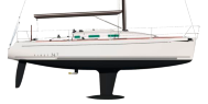
We’ve looked at simple square section bars. The exact same principles apply to ship design*. Boat hulls are designed with stability in mind. Here’s an example of cross-section through a boat hull:
| And aircraft too, but with slightly different forces. If you look at most aircraft, their wings are angled up slightly. This is called *dihedral, and helps keep the aircraft stable in the roll-axis. If a wing ‘drops’, then because of the angle, slightly more of the span of the wing is exposed to free-stream flow, this generates slightly more lift, correcting the drop. Again, it’s like a pendulum. | 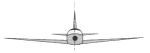 |
Righting Arms
Here’s a diagram of a boat heeling in water. As it leans, on one side of the ship, a section of boat that was under the water line is now OUT of the water, and a corresponding section on the other side is now IN the water.
From this, it’s clear to see that the center of buoyancy will shift towards the IN side. There is now more water displaced on this side of the boat. Just as we saw with the square section of the bar, this creates a righting arm, and the corresponding moment helps stablize the ship and push it upright again.
Improve Stability
| |As we’ve seen from above, there’s a couple of ways to makes boats more stable:|
-
We can lower the center of gravity. This is very popular with sailing yachts. A heavy mass (ballast) attached to the hull deep under water (this is especially important as sailing yachts tend to have tall masts) keeps the center of gravity very low. A negative consequence of this technique is that the draft (distance between the water line and the bottom of the keel) can be quite large. This restricts the boat, and it can’t operate in shallow water.
-
Making the boat flatter means that when it heels, the center of buoyancy moves a long way out creating a large righting arm making the torque to push the boat back vertical stronger.
-
Even more so than flattening the boat hull, you can employ floating outriggers to push the righting arm out further. This is the reason that catarmarans, and trimarans (multi-hulled boats) as so stable.
-
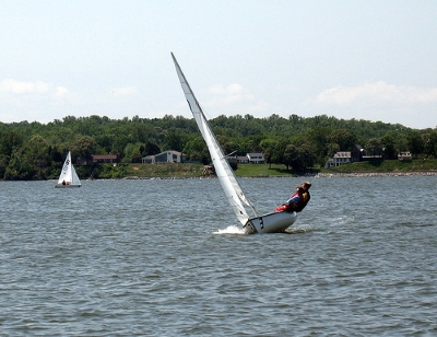
You can shift the center of gravity. Sailers are very familiar with leaning out to prevent boats rolling over.
Metacenter
| |Ship designers pay careful attention to something called a metacenter (and the corresponding metacenter height). The metacenter is the point of intersection between a vertical line through the center of buoyancy of a floating body such as a ship and a vertical line through the new center of buoyancy when the body is tilted. It needs to above the center of gravity to ensure stability.For small angles, the metacenter does not move much, and acts a little like the pivot point of a pendulum with the boat rocks under. Adjusting the height, in addition to providing safety and stability is a trade-off between making the boat ‘stiff’, or ‘tender’. This affects the ride of the boat (important for passengers and cargo), and what accelerations and forces act of it in rouger waters.|
The metacenter is the point of intersection between a vertical line through the center of buoyancy of a floating body such as a ship and a vertical line through the new center of buoyancy when the body is tilted. It needs to above the center of gravity to ensure stability.
You can find a complete list of all the articles here. Click here to receive email alerts on new articles.