This week I’m going to talk, not just about error detection, but also error correction.

We live in an imperfect world. Even when dealing with digital signals (on or off), sometimes errors can occur. Glitches can cause bits to flip. Hardware can fail. Signals can become distorted.

In the past I’ve written about ways of detecting that errors have occurred in digital signals. The most common way is with some kind of parity bit (don’t worry, I’ll refresh below what parity means if this is a new term for you). The addition of a simple parity bit allows the detection of a single flipped bit over the length of the word it is used over. It’s useful knowing that an error has occurred, but a simple parity bit cannot be used to repair a damaged signal. Also, if there is more than one error in the signal, these errors can cancel out to give no indication of error at all.
There’s a branch of mathematics that deals with methods of encoding redundant data into signals so that error detection and correction is possible, and this article will describe one method, invented by Richard Wesley Hamming, an American mathematician in 1950. His solution is now named after him as a Hamming Code. Before we get too deep into the math, let’s consider a couple of thought experiments.
Noisy signals
Let’s imagine you want to transmit the following coded message “I LOVE LUCY”.

The problem, however, is that the channel you wish to transmit the message over is very noisy and there is a small chance that any letter could be corrupted. If it was one error and it was the first letter that was messed up, you might appreciate that something was wrong, as “N LOVE LUCY” does not make sense. Similarly “I LRVE LUCY” looks nonsense. However, the message “I MOVE LUCY” might not raise an eyebrow, neither might “I LOVE LUCK”, and these are also just one character different.

If two letters change, you might get, “I ZZVE LUCY” which might suggest an error, whereas two letters changed to make “I HOPE LUCY” or “I WOVE LACY” or “I LOVE LADY” might not.
If three letters change, you might get, “IGNORE LUCY” (a space is just another kind of letter), which does not look like a mistake!

And what would happen if the message was not English text, but instead a password or just a string of data of which there is no dictionary or spellings to validate against? You might not even known an error had occured!

It would be good to know if the message was corrupted in some way. It would be even better if the message could correct itself.
What options do we have if we want a fairly high confidence that the message received is the one intended to be sent?
One option is to send the message multiple times. If errors occur fairly randomly distributed then they will tend to cancel each other out. Even using the contrived examples above (where the errors are not randomly distributed), if a message is transmitted multiple times, then by taking the modally occurring answer, letter-by-letter (the most frequently occurring in that slot), there is a good chance that the message can be corrected. It’s not foolproof, but it probably does work*. If you want a higher chance of sureness you can send the message more and more times; this, however, starts to rapidly become very inefficient as you’re repeating good information multiple times too.
|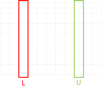 |Here on the left, we’ve sent the message multiple times. If, for each character, we take the most commonly occuring letter in each column, there is a good chance we’ll be able to reconstruct the source message.If the noise is mild, you can get away with repeating the message a small number of times. If the noise is heavy, more times would be needed (more of this later).|
If the noise is mild, you can get away with repeating the message a small number of times. If the noise is heavy, more times would be needed (more of this later).
*You can probably see that, mathematically, you can never be 100% certain. It could just happen that all the stars align (the wrong way), and every time a signal is corrupted it does so in a way that fools any error detection you have in place. Even if you computed a check-sum to valid your message, this checksum has to be transmitted too, and it could happen that the check-sum gets corrupted in a way also the makes it appear well formed.
Let’s continue our thought experiment by thinking in binary (which is what most digital computers use these days). Whilst binary might not be the, theortically, most efficient method to store data, because there are only two states (on the physiscal level); the presence, or not, of a signal, works well in digital computers where a signal is, or is not, present.
Parity
Imagine we need to transmit the following four bit word: 1101. Let’s see what we can do.
|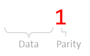 |Let’s first talk about a parity bit. A parity test is a method for detecting that a single error has occured. We can add an additional bit (a parity bit) to the end of our four bit word, to make a five bit binary word. Parity can be odd or even (it really does not matter which, as long as you are consistent). In even parity, what we say is that there should always be an even number of bits set in any word. As our data word, 1101, has an odd number of bits set, we set our parity bit to be 1 to make the count even. (If there were already an even number of bits set, the parity bit would be zero).|
After a message is received we can check to see if the parity is correct.
Try it out
Below is a four bit word. The fifth bit is configured to display an even parity bit.
Click on any of the data bits below to toggle its state and see the effect on the parity bit.
|You can see from this that, if any single bit, including the parity bit, changes state (flips from 1 to 0, or 0 to 1), then the parity will not be correct, and we will have detected that an error occured.Using the example 1101, the toggling on any single bit will move the number of set bits outside of parity to give an odd number of set bits. This is easy to detect. (Shown right).| |
|
Using the example 1101, the toggling on any single bit will move the number of set bits outside of parity to give an odd number of set bits. This is easy to detect. (Shown right).
| |This is great, and pretty efficient. We only need one bit per word. A minor issue, however, is if more than one error occurs in a single word. If there are errors in any two independant bits (or, actually an even number of errors, not just two), then these cancel out and there is no indication of an error.|
In the above examples, in each string of five bits, four are used for data. We can represent this as H(5,4)
We can adjust the number of bits in the data word as a trade off. With a small number of bits in any data word we’re much less likely to experience multiple errors, but lose efficiency. With H(4,3), there are just three data bits and so less chance of a double error occuring, however, one in four of the messages bits is parity, so we’re losing 25% bandwidth for this benefit.
With H(16,15), it’s much more data efficient, but the chances of a double error occuring is much higher.

Code rate is the second number divided by the first. The higher the code rate, the more efficient the transfer.
Two apples up on top
As we saw above, another option to detect errors is to duplicate the message. Instead of transmitting 1101, how about if we sent each bit twice? e.g. 11 11 00 11 (space added for effect). This is sometimes called by the name repetition code.
Ignoring, for a moment, the efficiency implications of this, what can this system detect? Because each bit is duplicated, then each adjacent pair of bits should match. If there is an error in any bit, then it will not match its twin; we will know that an error occured in that pair of bits. The issue, however, is that if we see a 10 or 01 we will not know is the message was supposed to have been 00 or 11. (Also, there is the a more troubling case if both bits flip, in which case we have no indication of any error.

Duplicating gives us single error detection, but no error correction. (If you think about it for a second, duplicating bits is just the same as adding a dedicated parity bit to every bit). We can call this H(2,1)
Three apples up on top
Taking this stage further, how about tripling each bit?
This helps us quite a bit. If there is a single error in any triplet, not only will we detect it (not all bits are the same), but we’ll be able to correct it. (Majority rules; there will be two of the correct bit, and an odd-one-out).

If there happen to be two errors in the same data bit, we’ll still get indication that an error occured, but it’s just that, if we chose to correct, we’d correct to the wrong value (majority rule), but at least know there was an error.
If there are three errors in the same bit, we’d get the bogus (inverted) answer.
We can call the tripling of data H(3,1).
Four Apples up on top
If we increased the duplication to four bits, we could detect and correct any error of one bit. We could detect, but not correct, an error of two bits (we have an even number of bits, so no majority vote). We would detect an error of any three out of the four bits, but bogusly correct it the wrong way.
With five repetitions, we can detect and correct all two bit errors, and detect three and four bit errors (but not corretly fix) …
This rapidly becomes very inefficient.
Hamming Distance
We can be more efficient if, when additng the additional error-correcting bits, they are arranged such that different incorrect bits produce different error results; then bad bits could be identified. This is what Hamming realized.
We’ll now introduce the concept of Hamming Distance, which is how many changes need to be made to a source to change it into something different.
The notion of edit distances and changes is a powerful concept in computer programming and used in many other areas, such as spell checking, typo correction, and file merging.
(A Hamming distance assumes the length of each word remains the same. If additions and deletions of bits/characters are allowed, then this is refered to as the Levenshtein edit distance. e.g. If you have a word “kitten” and want change this to “sitting”,then you can change the initial “k” to an “s” to make “sitten”, then the “e” to an “i” to make “sittin”, and finally add a “g”).
It’s easy to visualize Hamming Distances as directed graphs.
|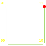 |On the left is a a graph for double repetition. With no loss of generalization, if we started off with signal 00, what is the minimum number of steps (errors), it would take to change the signal to 11? This is the Hamming Distance. For this configuration it is two.One possible (shortest) path is shown in the diagram on the left in green. (Of course, you can go backwards and forwards if you like, taking more steps!, but there is no way to get from 00 to 11, in less than two steps).It would take a minimum of two errors to produce a signal of which we could not detect an error.|
One possible (shortest) path is shown in the diagram on the left in green. (Of course, you can go backwards and forwards if you like, taking more steps!, but there is no way to get from 00 to 11, in less than two steps).
|For a triple repetition we can depict this as a cube. To change from 000 to 111 takes a minimum of three steps.Again, it does not matter what order (path) you take, and if you ‘go back’ as well as ‘go forward’, but the minimum number of steps is three.|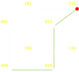 |
|
Again, it does not matter what order (path) you take, and if you ‘go back’ as well as ‘go forward’, but the minimum number of steps is three.
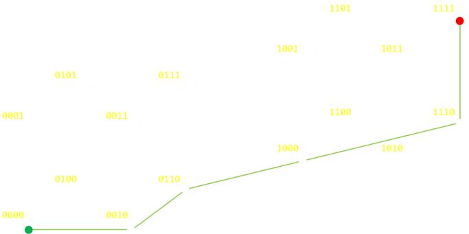
For quadruple repitition, we need to depict this as a tesseract (a ‘cube’ in 4D).
Hamming Distance (more advanced geekery)
The above examples show the extreme case of moving from one vertex of a graph to the other (inverting all the bits). A Hamming distance is just as valid between any two nodes on the graph and decribes the (minimum) number of steps; the minimum number of bit flips, it would take to traverse from one node to the other. Below are two random examples:
If you are familiar with boolean logic you will appreaciate that an easy way to determine the Hamming distance is to XOR the two values, then count the number of set bits (the last step is sometimes called a bit population count, or sideways sum, or a Hamming weight; some microprocessors have this as a fundemental instruction).
If you’ve studied geometry, the Hamming distance is the same things as a Manhattan (taxi-cab) distance between two vertices.
Back to error correction
We now have all the pieces we need to describe the various error detection and correction algorithms. We can describe them in terms of Hamming distances they can detect, and into which they can correct. Vanilla parity (simple duplication) has a Hamming distance of two; by changing two bits it’s possible to get into a state that it’s impossible to tell an error occured (It would take two independent errors to get into a state where we could not detect an error had occured). With triplicate bits, this distance is three (and we’ve reduced efficiency as only one third of the total bits are carrying our signal).
Hamming’s research focussed on making the Hamming distance as high as possible but at the same time increasing the efficiency (having as high a ratio as possible of data to error deteting bits.
Hamming Code Algorithm
The key to the Hamming algorithm is the creation of a collection of parity bits that can be used to uniquely identify any single bit error.
Each parity bit allows the address space to be broken into two halves (if set, the error is one half, if not the other half), like a mask. Using powers of two these masks can be defined. (There is a very interesting, and very geeky, puzzle using this principle called The impossible Escape, which uses coins and a chess board). The first parity bit collects data about the parity of odd/even bits. The second parity bit if groups of two (two present, skip two, two present …), then next in groups of four, …
We’ll describe the algorithm first, then experiment with it.
Parity bits are inserted, interstitially, between the data bits, and each power of two is a parity bit. The number of parity bits is, therefore, defined by the number of data bits to make the complete word.
-
The first parity bit represents parity for all data bits with the least significnat bit set when the number is represented as binary (20) e.g. 3,5,7,9,11 … (itself being in bit position 1).
-
The second parity bit represents parity for all data bits with the second least significant bit set (21) e.g. 3,6,7,10,11 …
-
The thirs parity bit represents parity for all data bits with the second least significant bit set (22) e.g. 5,6,7,12,13,14,15 …
You can see this represented in the table below, which shows the pattern for the words up to fifteen bits length (eleven data bits and the required four parity bits). This system can be extended out as long as necessary to encode as many bits as needed.

Each bit has a unique (binary) combination of parity bits for itself.
To check for errors, we simplye need to check each of the parity bits. The pattern of errors, called the error syndrome, identifies the bit in error. If all parity bits are correct, there is no error. Otherwise, the sum of the positions of the erroneous parity bits identifies the erroneous bit. For example, if the parity bits in positions 1, 2 and 8 (P1, P2, P4) indicate an error, then bit 1+2+8=11 (D7) is in error.
(Of course, if only one parity bit indicates an error, the parity bit itself is in error!)
Below is a short seven bit word comprised of four data bits and the required three parity bits. You can click on any of the data bits and the parity bits will be calculated for you. This is H(7,4), and the rate is 4/7 ≈ 0.571
|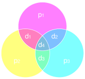 |If you are familiar with sets and Venn diagrams, these parity bits and their relationships can be shown in the diagram on the left.Parity needs to be correct in each circle, and a distinct mismatch of any combination of parity bits uniquely identifies a digit.|
Parity needs to be correct in each circle, and a distinct mismatch of any combination of parity bits uniquely identifies a digit.
Here’s a longer word containing eleven data bits and the required four parity bits. It is also interactive. You can’t click on the blue parity squares to change them: These values are derived from the other data bits. This is H(15,11), and the rate is 11/15 ≈ 0.733 |0|0|0|0|0|0|0|0|0|0|0|0|0|0|0| |P1|P2|D1|P3|D2|D3|D4|P4|D5|D6|D7|D8|D9|D10|D11|
Now that we know how the encoding works, lets see how we apply this knowledge to decoding and correcting. If the word comes through unscathed, all parity bits will be correct. However, if the message is damaged then parity will be disrupted. As we know that each data bit is addressed by a unique combination of parity bits, we can use this to find the flipped bit.
Below is a simulation of H(7,4). The top row shows the pure data we wish to transmit (You can press the ‘Randomize’ button to generate different, random starting words). This top row is generated by creating a random 4 bit number and correctly calculating the parity for this number.
The row below (in red) represents the signal received at the other end of the, noisy, transmission. Initially it’s correct, but you can click and toggle the state of any/all of the bits to represent an error in transmission.
Below this is shown the detected parity errors, and these bits identify the bit with the error. |0|0|0|0|0|0|0||Randomize| |P1 = OK|P2 = OK|P3 = OK|
The recreated signal is shown on the bottom line. The bit that has been corrected is rendered in green.
You can see that, if there is an error with any one of the received bits, the original signal can be recreated without issue. This is very, very cool. Not only have we detected an error occured (an issue with at least one parity bit), but we were able to fix it.
You can experiment with errors of more than one bit by toggling more than one of the red numbers. H(7,4) is able to detect all one bit, and all two bit bit errors, but is only able to correct for one bit error (and if you attempt to correct when there are two errors, you will bogusly correct the signal).
In H(7,4), two bit errors are indistinguishable from one bit errors.
However, there is another neat trick that can be applied to resolve this …
|It’s possible to include an additional (overall) parity bit which is applied to the entire H(7,4) word to make an H(8,4) code.This increases the Hamming distance from three to four and allows the algorithm to correctly detect two bit errors.The H(8,4) is often referred to as SECDED, which stands for Single Error Correction, Double Error Detection. It can seamlessly fix any single bit error, and identify that a double error has occured (though it cannot fix). This is a big improvement of the H(7,4), which could do one or the other, but not both.Memory boards for computers servers, and other mission critical computers, typically use memory boards arranged in SECDED configurations, often as H(72,64) format. This is why, if you look at DIMMs for servers, they will probably have an odd number of memory chips on one side! These memory boards are called ECC (Error Correcting), and allows servers to not lose data if the odd glitch is encountered, and still be able to flag it as as issue to those who maintain them.|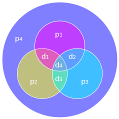 |
|
This increases the Hamming distance from three to four and allows the algorithm to correctly detect two bit errors.
Memory boards for computers servers, and other mission critical computers, typically use memory boards arranged in SECDED configurations, often as H(72,64) format. This is why, if you look at DIMMs for servers, they will probably have an odd number of memory chips on one side!

You can find a complete list of all the articles here. Click here to receive email alerts on new articles.